
Having laid the foundation in the last article, it is now time to do a more detailed review of some of the fittings that are associated with bowsprits. I’ll adopt here the same approach that will be used for the remainder of this series of articles, which runs roughly as follows. For items such as boat equipment, there are three necessary conditions for success. First, and most importantly, the part needs to be strong enough to perform its function for a satisfactory length of time, i.e. the “engineering” needs to be sorted out. In the area of traditional rigs, we’ll see that empiricism (trial and error) tends to hold sway over science at the moment. Secondly, because boats are fairly complex things, each component needs to be arranged so as not to interfere with others, or to be able to fulfill a secondary function, or to work together with others in a consistent fashion. In other words the practical aspects of the component need to be addressed. Thirdly, it has to look right in relation to its surroundings.
The engineering aspect I’ll give some guidance on wherever possible, since it is often neglected, sometimes to a dangerous degree. You will probably have a handle on the practical aspects, but they are worth re-stating if only for completeness (or to stimulate debate of the “appalled from Maldon” type). Since surroundings, fashions and perceptions vary so widely, I’m going to leave aesthetics to you!
Anyway, let’s get on with bowsprits. As we saw last time the purpose of the thing is to extend the sailplan beyond the confines of the hull. The load which it needs to withstand is that generated in the jibstay or forestay by the foresail and/or the mainsheet via the peak halyards and/or the running backstay(s) and/or anything else one can think of. And herein lies the nub of the problem: it is not possible to get a “scientific” design load for a jibstay on a traditional rig. A few souls can begin to approach such an ideal for the – much simpler – Bermudan rig, but even then tend to commit the frequent, but pardonable, sin of believing the numbers when they get them. For us ordinary mortals rules of thumb for jib/forestay sizing necessarily prevail, and generally take the form of “largest shroud size plus one”. As we will see in later articles, shroud sizing is somewhat more susceptible to analysis even for traditional rigs.
Bowsprit loads
However, having got to a forestay load by whatever means we can now at least be a little more clever about checking the other parts of the bowsprit arrangement.This is because the bobstay and bowsprit loads can be deduced from the forestay load by resolving the forces, and from there it is possible to get some useful guidance for sizing the various components. For a “modern” gaffer such as the Cornish Crabber or the Norfolk Smuggler, the bobstay tension is 1.3 to 2 times the forestay tension, and the bowsprit compression 1.5 to 2.3 as much. For more traditional rigs such as Falmouth Oyster boats or Essex Smacks the ratios go up to about 3 times the forestay load because of the relatively longer bowsprit and narrower staying angles. That provides the start point for assessing the various components as follows.
Bowsprit
Excepting very short ones the way in which bowsprits fail under service loads is in buckling rather than compression. In buckling, the longer the bowsprit, the lower the force it can resist. (I’m going to deal with buckling in more detail when we come to masts.) If you know the maximum load it can bear and the ratio between bowsprit force and forestay force, you can work out the maximum load that the forestay can safely bear, and compare that either to the breaking load of the wire or a “real life” guesstimate of maximum loads on the stay. One upshot of this analysis is that – in theory at least – you would be better off with a bowsprit starting at the stemhead since that would reduce the length of the spar hence increasing the maximum loading possible for a given diameter. It would also make retraction easier if you just had to “unplug” the bowsprit. I can’t help feeling, though, that the everyday problems caused by a bowsprit flopping about would outweigh the theoretical advantages.
More useful is the fact that bowsprit shrouds will raise the maximum load by a factor of four, because of the change in fixity, so if you think your shroudless bowsprit is a bit twitchy, that is an easy fix. A tentative conclusion here is that the purpose of the bowsprit shrouds is primarily to increase the load bearing capacity of the bowsprit by changing its mode of failure in buckling. I should emphasize that I am ignoring non-service loads – like driving into a wave or quay – and lateral loads from the jib. The first are not explicitly designed for, the second are always small by comparison with the vertical loads.
Bobstay
The main thing about bobstays is to make them strong enough, and a bit more – he says stating the obvious!
Using the ratio of bobstay force to forestay force, and the chart below, you can develop a consistent set of equipment for your bobstay, whether it be wire, chain, rope or a combination of these. Please also check the breaking loads of any blocks you may be using. It is important that the bobstay is made of flexible material since mooring warps or anchor chains will tend to rub against it, unless you develop a scheme for raising it out of the way. Plastic tube is often used as a chafe protector on the bobstay, which is a good scheme as long as you allow some provision for drainage at the lower end to avoid corrosion. Perhaps the easiest way of doing that is to cut the tube at an angle so that water can run out of the end.

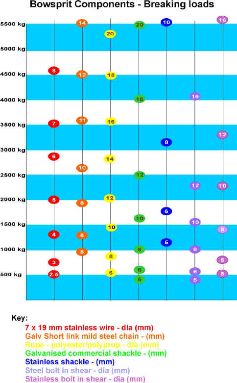
Example: Forestay Maximum Load 1000kg, Bobstay Maximum Load 1500kg, Bowsprit Maximum Load 1800kg
Forestay wire 4mm 1 x 19 S/S – breaking load 1400 kg
Bobstay (1500kg) 6mm 7×19 S/S or 6mm galv chain or 10mm rope, using 10mm galv or 6mm stainless shackles
Bobstay fitting(3000kg) use 2 x 12mm steel bolts or 2 x 10mm stainless bolts or 16mm galv eyebolt
Cranse iron (1800kg) if through bolted 1 x 10mm or 2 x 8mm stainless bolts 375 sq. mm surface area of shoulder required*
Heel fitting (1800 kg) bolt down with 4 x 6mm steel bolts or 4 x 6mm stainless bolts,would probably use heavier anyway if used for mooring. Bowsprit retaining pin, 12mm steel or 10mm stainless
* In Douglas Fir, the “Shoulder strength” in kilograms = 4.8.(d-t).t
where d = Bowsprit diameter in mm, t = shoulder depth in mm
Slightly less obvious is the need to make the bobstay stiff, so that the outboard end stays in roughly the right position. You can see from smacks and similar working craft how the bowsprit is steeved down when not under load. As the rig powers up, the end of the bowsprit lifts into the right place. This practice isn’t the “proper way to do it” so much as a reflection of the materials available for the bobstay. With traditional rope tackle whose fall is led along a long bowsprit, you could never achieve the stiffness required to keep the cranse iron in place without some pre-tension. Here is a good example of where modern rope can work wonders. Next time you re-rig your bobstay, try Kevlar, Spectra, Dyneema or one of the other low stretch, high-strength ropes. You set up the bowsprit, and it stays there
Bobstay Fitting
This is a very highly loaded item placed inevitably at the worst possible place from the point of view of corrosion. If it lets go, you may have a large amount of actual or financial inconvenience. I suggest that you size it for at least twice the bobstay load – and the chart gives some guidance here. What tends to be fitted is either an eyebolt, which is fine for smaller craft, or a U-Bolt. One snag with these last is that it is sometimes hard to get them with long enough “legs” to pass through the stemhead of wooden craft. Another is that it is quite difficult to drill two long holes exactly parallel to fit the thing. A more pragmatic solution is to use an eyeplate which is fastened to the stem with two bolts. That way a small amount of inaccuracy in drilling the fastener holes will not matter. And please always fit a backing plate, or at least hefty washers.
Cranse Iron
A cranse iron has the job of transmitting the rigging loads into the end of the bowsprit, and must therefore be able to resist the full bowsprit load without sliding up the spar. There are a number of ways of locating it, the conceptually easiest being to cap the end. This has the advantage of strength, but has the drawbacks that you can’t mount a traveller sheave outboard of it, and more importantly that accumulated rainwater can cause rot to start at the end of the bowsprit.
An option which avoids those drawbacks is to mount the cranse iron on a shoulder on the bowsprit, and I’ve given some guidance on the required shoulder size in the chart. A variant of mounting on a shoulder which we adopted recently for the Brock 24 was to make a conical cranse iron. The main purpose of doing that was to allow for the cranse iron to be knocked off during retraction, but guaranteeing a snug fit under service loads. It was felt that a parallel cranse iron would be either too loose to be secure or too tight to remove. Finally, you can through-bolt the thing, and the chart gives a feel for the size of fasteners you might use.
With regard to the design of it, if you believe the numbers, then the lower lug of a cranse iron should be stronger than the upper by a factor of 2 or 3. In practice, this tends not to be the case. That would indicate that it is the lower lug that will fail first, or show signs of failing, but I have to confess that in my own experience it is much more common for bobstays or their fittings to let go. If any readers have experience of cranse iron failure, I’d like to hear of it to see how they do fail. Another area to tackle is to provide enough room on the upper lug for both the forestay and furling gear if fitted. Good options are either to have a long cranse iron – e.g. Norfolk Gypsy – or a separate small band for the furling gear, a sort of non-travelling traveller. It is not such a good plan to have a top lug which overhangs the main band since that will tend to concentrate stresses just at a point where there are likely to be imperfections in a weld or casting.
Heel Fitting
To keep the forward accommodation space clear, modern boats with bowsprits tend to use a distinct fitting bolted to the deck rather than the traditional samson post or bitts running through to the kelson. Since the loading is predominantly fore-and-aft, that is a reasonable thing to do so long as the mounting bolts are sufficiently numerous and strong. Again have a look at the chart for guidance. In many ways, the move to a heel fitting has opened up options for retraction which didn’t exist before, or didn’t need to exist before, but which are nowadays almost mandatory. With a tenoned attachment into a samson post, the bowsprit has to be moved forward to release it, and so all the stays need to be extendable or disconnectable to allow that. The Cornish Crabber arrangement, with an open top and upright after face, allows the bowsprit to be lifted at the after end before retraction. The only snag is that you need to take some tension off the bowsprit before you can lift it. On the Norfolk Smuggler, we got around this by angling the after face of the heel fitting and the bowsprit so that it can be raised out of the fitting, and re-tensioned by pushing the bowsprit back into the fitting with a boot or other blunt instrument. It does work! On both of these boats the aim is to retract the bowsprit onto the side decks or cabin roof, so the rigging and cranse iron could remain fitted. On the Brock 24, with a deep foredeck well, and the bowsprit fitted through the bulwark, such a scheme was not possible, so the slightly unusual approach of withdrawing the bowsprit through a porthole into the cabin (and then onto the deck) has been adopted. Hence the absence of an after plate on the fitting, and the need for a readily removable cranse iron.
The other benefit from using a heel fitting of this type is that other aspects can be incorporated, for example a mooring cleat on the Crabber or lifeline attachments on the Brock 24. The way in which the details of heel arrangements have developed is a good example of how fittings for traditional rigs have evolved in response to today’s requirements; in this case for maximum accommodation space, and ease of retraction.
Next time I’ll get onto gammon irons, travellers, anchor stowage and foredecks. In the meantime, if your boat has a bowsprit, could you please check the bobstay, its attachments and its components. It really is most upsetting to have one let go!