
The next item on the agenda is booms. Those of you with sprit rigs, bawleys and Drascombes can skip this article with impunity. For the benefit, I hope, of the rest of us, I am going to look in a simplistic way at the engineering of booms in this article, and the implications for the fittings and arrangements in the next. As with many aspects of the rig the boom, its design and fittings are ideally considered all of a piece.
Let me make a start, as I have tried to do wherever possible in this series of articles, by looking at the loading on the boom, and so working out its arrangement. I am going to take as my example boat a 30ft gaff cutter, whose mainsail foot is 5.4m long (yes, that’s right, think in feet and work in metres!) with a mainsail area of 34 square metres. Current thinking assumes that the primary load on the boom is a distributed lateral load from the mainsail. This causes the boom to bend, and that bending is counteracted by the kicking strap and the mainsheet.
Working to Rule
Two rules have been developed. The first, the Nordic Boat System (NBS) involves the design heeling moment (we encountered this when looking at mast sizing), the length of the boom and the height of the centre of effort of the sailplan (Ref 1). The second, Bureau Veritas (BV), involves sail and boom dimensions (Ref 2). For comparison, I’m going to look at a hollow wooden spar of wall thickness of 19mm and an aluminium spar of 3mm wall thickness. I’ll also assume that a kicking strap is fitted. The diameters in millimetres which result are as follows:
| Wood | Aluminium | |
| NBS | 240 | 180 |
| BV | 220 | 180 |
These answers are about the same for both rules, which is encouraging, but look rather large. To revert to inches again, the wooden booms are about 9” in diameter, the alloy ones about 7½” dia. This is not right for the boom on a 30ft gaffer. What have I done wrong? Have I used a rule of thumb beyond its range of applicability? Both rules apply to modern Bermudan rigs with relatively high aspect ratios and short booms fitted to relatively light displacement hulls. If I “convert” the sailplan to Bermudan the diameters come down to 193mm and 153mm dia. These are still large, but approaching the bounds of reality, particularly for aluminium. I begin to wonder whether in practice this is a rule of thumb geared to the selection of aluminium sections for the booms of modern yachts. That is fine as far as it goes, but doesn’t really help to develop an understanding of traditional rigs. Let me take a step back and see if it is possible to work from more basic considerations.
Back to Basics
Thanks to Harken, I can estimate the forces in the mainsheet for a given sail, using a formula given in Ref 3. Just so I don’t fall into the same trap as before, if I calculate the force for both Bermudan and gaff options they both work out to be 500kgf. Let me assume no kicking strap, and that the mainsheet force resists an evenly distributed load along the boom – Fig 1 shows the scheme.

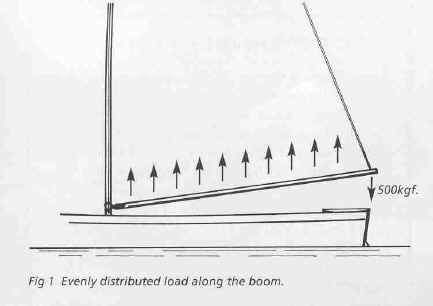
What happens now? In the worst case – no kicking strap and the mainsheet at the very end of the boom, the diameters work out around 200mm and 160mm for wood and aluminium respectively. This still doesn’t seem right. Why not? Because a) the boat in question exists, has a hollow wooden boom of 110mm dia, and has covered thousands of miles in all weathers, and b) booms are typically about 60-70% of the mast diameter, which we worked out as about 170mm some articles ago, and again that gives around 110mm. I can’t help feeling the assumption that the major loading is due to bending is wrong.
If you leaf through more or less any yachty book or magazine and have a look at the mainsails depicted, you can see that rather than a distributed load along the boom, the reality is much more like point loads at the tack and clew. This is certainly true for:
– loose footed sails, of traditional type or more modern variants for example when in-mast reefing is used
– any sail when slab reefed, since the sail ties do little except tidy the bunt of the sail
It may also be true for mainsails even when laced or continuously attached to the boom. If you look at the creases in the sail, it would seem that the major loads are being distributed radially from tack and clew, with relatively little sideways loading from the middle of the foot.
So what? So a better approximation to the force in the boom is not sideways bending, but a compressive force along the boom. Let me try a different loading example, using the same mainsheet load as before, and with a few assumptions, I can get to the loading conditions sketched in Fig 2.

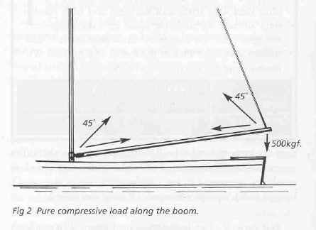
What happens now? With a factor of safety of 5, both the wooden and aluminium spar end up with diameters of 104mm. Well there we are then, that solves that.
Not quite, because however hard you try, there is always going to be an element of bending present. This might result from the mainsheet take-off not being directly below the clew, for example when the sail is reefed, or if the blocks are distributed along the boom. In addition, a kicking strap will necessarily exert a lateral load, though not necessarily when close-hauled because of the pull of the mainsheet.
Loads and Loads
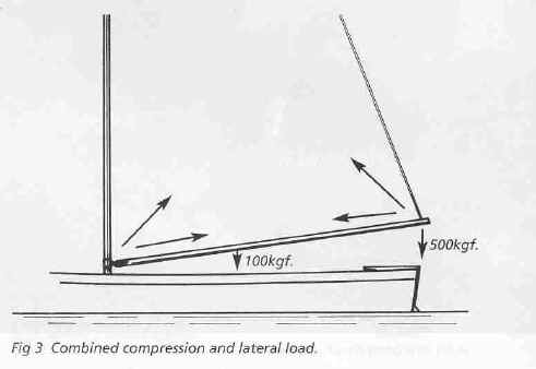
So let me do the sums again with a combined end and side loading, making some heroic assumptions about the side loading. Figure 3 shows what I am trying to do, and the sideways load represents either a kicking strap, or a mainsheet set along the boom forward of the clew (perhaps aligned with the forwardmost reef cringle). Now we get 124mm/104mm for wood /aluminium, which is somewhere in the realms of reality.

Now I’m not going to suggest for a moment that MacPhail’s theory for boom sizing is in any sense “correct” and should be used right away by all designers; it hasn’t been developed with anything like the rigour needed to make it safe. But it does illustrate a few things, namely,
– the use of rules of thumb beyond their range of applicability. Both the NBS and BV rules are very sensitive to boom length. This means that a traditional rig, with characteristically long boom, tends not to fit the model. As we discussed many articles ago, rules of thumb with implicit (or even wrong) assumptions can be very misleading
– the choice of loading assumption affects the choice of materials. Capability to resist bending depends on the size and shape of the cross section, and the strength of the material involved. Resistance to buckling is a function of the cross section and the stiffness of the material. Aluminium is four times heavier than wood, four times stiffer, but eight times as strong. As we have seen from the numbers above, the less important you assume bending to be, the more important stiffness becomes, and the more useful wood becomes as a material for spars. For a quick foray into strength and stiffness, see the section on the next page.
– Some say that a heavy boom on a gaffer is a good thing to control the shape of the sail. I have seen some where the thing has been shape somewhat like an elongated baseball bat, with the thin end toward the gooseneck. But even if you make the wooden boom solid in the examples above, the weight represents some 5 to 10% of the force in the mainsheet. How much twist will that control?
– the more you can go for compression and avoid bending in your spars, the better seems to be the conclusion reached for bowsprits, masts, booms and (to a lesser extent) gaffs. If that is so, then the primary need is for a stiff material. About the stiffest around is carbon fibre, some 40 times stiffer than wood. It would be interesting to rig a gaffer with carbon spars, and I have just such a project in mind. I’ll keep you posted.
But enough of such esoterica, next time I’ll have a look at the practicalities of the fittings.
References
1. Larsson & Eliasson Priciples of Yacht Design Adlard Coles 1994
2. Claughton et al Sailing Yacht Design Longman 1998
3. 2002 Hardware Catalogue, Harken Inc USA
Stress, Strain and Stiffness
To understand the use of materials it is helpful to know a little about these things
Stress is the amount of force acting over a particular area. If a 1 ton boat is suspended by a wire of a cross-sectional area of 1 inch, the stress in that wire is 1 ton per square inch. It doesn’t matter what the wire is made of, the stress will be 1 ton per square inch. By using this concept, the strengths of different materials can be related. You can have a large piece of wood as strong as a smaller piece of steel but, because of their different cross-sectional areas, the stresses at which they break would be very different.
Strain is defined as the extension per unit length, usually expressed as a percentage. So if our wire was initially 100m long, and extended to 102m under load, the strain is said to be 2%. The amount of strain at fracture can give us a feel (but no more) of the brittleness of a material. Pottery breaks at about 0.5% strain, piano wire (steel) at 5%, mild steel at 30%, rubber at 2-300% and so on. Typical working stresses for metals induce strains of about 0.1%.
And finally, stiffness. Return to our 1 ton boat on the 1 inch wire. If the wire were steel, it would barely stretch at all. If it were wood it would stretch more, nylon more still, and rubber might simply keep extending to leave the boat on the ground! Each material under the same stress shows different strains. Divide stress by strain and you have a measure of stiffness – steel has a high value, rubber a low one. Stiffness – referred to as “Modulus of Elasticity” or “E” – stays fairly constant for a given base material irrespective of the alloy or type. So wrought iron, mild steel, cast iron, stainless steel and high tensile steel all have virtually the same E. Taken together, strength, i.e. the maximum stress permissible, and stiffness give a fair idea of the nature of a material. To illustrate that look at the table below
| Strong | Weak | |
| Stiff | Carbon Fibre | Raw Spaghetti |
| Flexible | Nylon | Cooked Spaghetti |